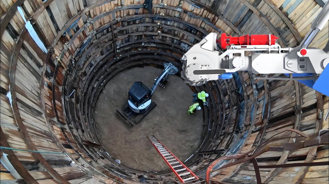
Water inrush is a common and high-risk issue during shaft excavation, potentially leading to reduced construction efficiency, surrounding rock instability (such as collapse), equipment damage, and even accidents. Addressing water inrush requires adhering to the principles of "prevention first, categorized management, and dynamic monitoring." Targeted technical solutions should be implemented based on geological conditions (such as aquifer type, water pressure, and water inrush volume) and the construction phase. The following are core solutions based on engineering practice:

I. Early Prevention: Early Exploration and Risk Management
1. Detailed Geological Survey
Pre-construction, through drilling and geophysical exploration (such as seismic and electrical prospecting), the distribution of aquifers, water pressure, permeability, and the location of fault fracture zones in the strata through which the shaft will penetrate should be determined. A detailed hydrogeological profile should be drawn to identify potential water inrush points (such as sandstone aquifers, karst caves, and zones with dense fractures).
2. Advance Detection and Forecasting
During excavation, a "short-segment excavation, advance detection" model is employed. Every 5-10 meters (adjusted based on ground stability), advance boreholes (50-100 mm in diameter, 3-5 meters beyond the current tunnel face) are used to monitor the hydrological conditions ahead. If the borehole water inflow exceeds 5 m³/h or the water pressure exceeds 0.5 MPa, excavation is immediately halted and pre-treatment measures are initiated.
3. Pre-drainage and Pressure Reduction (Applicable to High-Pressure Aquifers)
If a deep, high-pressure aquifer (such as an artesian aquifer) is detected, dewatering wells can be constructed in advance around the shaft (the number is calculated based on the water inflow and the depth exceeds the aquifer floor). Deep well pumping can be used to lower the water level in the area, placing the excavation face in a "drained stratum" and reducing the probability of water inflow.
II. Grouting Water Blocking Technology (Core Anti-seepage Method)
1. Pre-grouting of the Working Face
① Grouting holes are constructed 10 meters before excavation reaches the aquifer, penetrating the aquifer and extending 5 meters into the aquiclude, forming a closed curtain.
② The grouting pressure is controlled at 0.5 to 1.2 times the hydrostatic pressure, and grouting is performed in stages to seal cracks (large cracks are injected first, followed by small cracks).
③ Results: In a typical case, water inflow was reduced from 9.6 m³/h to 0.5 m³/h.
2. Directional Drilling Grouting
For deep, high-pressure aquifers, S-hole directional drilling technology is used for precise grouting. Cement-water glass dual-liquid grout or chemical grout is used.
3. Behind-the-wall Grouting Reinforcement
After the wellbore is poured, grout is injected behind the wall through a pre-reserved grouting pipe to fill the gap between the lining and the surrounding rock.
III. Drainage System Design and Emergency Management
1. Staged Relay Drainage
① During reverse slope construction, a pumping station should be installed every 300 meters, equipped with an amphibious, wear-resistant pump (lift of 150 meters or more) and emergency backup pipelines.
② The pumping station capacity should be designed based on 120 minutes of normal water inflow, with a temporary sump immediately adjacent to the tunnel face (≤50 meters).
2. Staged Interception of Water Inrush
① Uphill Section: A mortar-lined drainage ditch should be installed 1-2 meters from the sidewall.
② Downhill Section: A sump and submersible pumps should be used for staged drainage.
3. Emergency Drainage Reserve
High-pressure, corrosion-resistant composite pipelines and high-powered sand removal pumps should be installed to handle sudden water inrush (e.g., friction anchor drainage and drainage from water collection holes).
IV. Water Inrush Control in Special Strata
1. Freezing Method
Freezing the aquifer with -25°C salt water creates a temporary freeze barrier to block water flow. This method is suitable for quicksand or high-pressure aquifers.
2. Composite Lining Waterproofing
① Initial spraying of concrete → Installation of waterproofing sheets (thermal welding) → Secondary concrete lining, with joints staggered by at least 0.5m.
② Key Points: Waterproofing sheets should be padded with plastic sheeting to prevent puncture, and waterstops should be fixed at right angles and straightened in sections after demolding.
Key Points: First, survey the water source → Pre-grouting to intercept the flow → Staged drainage to provide a backup → Structural waterproofing reinforcement. Complex strata require a combination of freezing/curtain methods, supplemented by real-time monitoring to mitigate the risk of emergencies.


