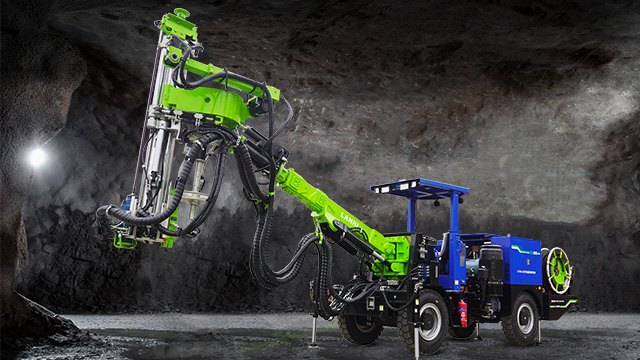
The performance of a tunnel bolter depends on the coordinated operation of its various systems. These core components include the power system, drilling tool system, propulsion system, operating system, and auxiliary systems.

1. Power System
① Pneumatic: This system consists of an external air compressor, pneumatic motor, and air control valve. Compressed air, regulated by the air control valve, drives the motor and provides propulsion.
② Hydraulic: This system consists of a hydraulic pump (driven by an electric motor or diesel engine), a hydraulic motor, a hydraulic cylinder, and a relief valve. The hydraulic pump delivers high-pressure oil, which is controlled by a valve block to control the motor speed and cylinder propulsion speed.
③ Electric: This system consists of a three-phase asynchronous motor, a speed reducer, and a frequency converter. The speed reducer reduces the motor speed and increases the torque, while the frequency converter enables stepless speed regulation.
2. Drilling System
The drilling system is the core component that comes into direct contact with the rock and determines drilling efficiency and hole quality:
① Drill rod: Commonly made of high-strength alloy steel pipe (40CrMnMo), with a diameter of 25-50mm and a length of 0.5-2m (can be spliced), it has slag grooves (spiral or straight) on the surface to remove rock cuttings.
② Drill bit: Select according to rock hardness:
① Soft rock (Grades IV-V): Slotted or cross-shaped alloy drill bits (low cost, average wear resistance);
② Medium-hard rock (Grade III): Ball-tooth drill bits (tungsten alloy teeth, strong impact resistance);
③ Hard rock (Grades I-II): Polycarbonate diamond composite (PDC) drill bits (high hardness, long life, and high drilling accuracy).
3. Propulsion System
The propulsion system ensures uniform feed speed of the drill tool and provides stable drilling pressure:
① Pneumatic propulsion: The drill tool is driven forward and backward by a pneumatic cylinder. The propulsion force is low (1-5 kN) and is suitable for shallow holes.
② Hydraulic propulsion: The propulsion is driven by a double-acting cylinder. The propulsion force is adjustable (5-50 kN) and can adapt to rock with varying hardness.
③ Mechanical propulsion: A few electric drills use a lead screw nut for propulsion. This provides high precision but slow speed and is suitable for precision drilling.
4. Operating System
The operating system controls the start and stop, speed, propulsion direction, and angle of the drill rig:
① Manual operation: Small drills are equipped with a handle and knob to manually control the air valve or hydraulic valve.
② Semi-automatic operation: Outrigger drills are equipped with a hydraulic pilot valve for easier operation and adjustable propulsion speed.
③ Fully automatic operation: Tracked rigs are equipped with a PLC control system. Parameters (drilling depth and angle) are set via a touch screen. Laser guidance is used for positioning, eliminating the need for manual intervention.
5. Auxiliary Systems
Auxiliary systems enhance operational safety and environmental performance:
① Dust Removal System: These systems are available in dry (bag filters, cyclones) and wet (water spray) types, collecting dust generated by drilling (dust concentration during tunnel construction must be ≤2 mg/m³ to prevent silicosis).
② Debris Removal System: Pneumatic drills use compressed air to remove rock cuttings, while hydraulic drills can be equipped with a slurry circulation system (wet deslagging, suitable for surrounding rock prone to collapse).
③ Stabilization System: Crawler drills are equipped with outriggers or counterweights to prevent the entire machine from tilting during drilling. Outrigger drills are equipped with an inclinometer to ensure the drilling angle meets design requirements (typically, the angle between the anchor bolt and the surrounding rock is ≥75°).


